What Are You Looking For?

Flexible Magnets in Sensor Applications – Technical Support (Ferrite vs. NdFeB)
1. Overview: Why Use Flexible Magnets in Sensors?
In non‑contact sensors, flexible magnets are widely used as the magnetic source in combination with Hall elements, magnetoresistive elements, or coils to detect position, speed, angle, or direction. Compared with sintered magnets, flexible magnets offer the following advantages:
The two most common rubber magnet materials for sensor applications are Ferrite Flexible Magnets and NdFeB Flexible Magnets. Their magnetic field strength differs significantly, making them suitable for different sensitivity and cost requirements.
| Property | Ferrite Flexible Magnet | NdFeB Flexible Magnet |
|---|---|---|
| Remanence Br | 210 – 270 mT (anisotropic) | 550 – 800 mT (isotropic / anisotropic) |
| Typical surface field (1mm thick, 0.5mm gap) | 80 – 120 mT | 180 – 250 mT |
| Max. energy product (BH)max | 8.8 – 13.6 kJ/m³ | 44 – 96 kJ/m³ |
| Intrinsic coercivity HcJ | 148 – 319 kA/m | 600 – 876 kA/m |
| Operating temperature | -40°C ~ +80°C | -40°C ~ +120°C (some grades +150°C) |
| Minimum stable pole pitch | ≥ 3 mm | ≥ 2 mm (precision ≥1.5 mm) |
| Temperature coefficient of Br | -0.2 ~ -0.3 %/°C | -0.07 ~ -0.13 %/°C |
| Cost | Low | Medium (3‑5× ferrite) |
| Typical sensor applications | Low‑resolution speed sensors, proximity switches, magnetic reed switches | High‑precision encoders, automotive wheel speed sensors, linear displacement sensors |
💡 Key conclusion:
2. Comparison of the Two Flexible Magnet Materials (Sensor‑Specific)
| Property | Ferrite Flexible Magnet | NdFeB Flexible Magnet |
|---|---|---|
| Remanence Br | 210 – 270 mT (anisotropic) | 550 – 800 mT (isotropic / anisotropic) |
| Typical surface field (1mm thick, 0.5mm gap) | 80 – 120 mT | 180 – 250 mT |
| Max. energy product (BH)max | 8.8 – 13.6 kJ/m³ | 44 – 96 kJ/m³ |
| Intrinsic coercivity HcJ | 148 – 319 kA/m | 600 – 876 kA/m |
| Operating temperature | -40°C ~ +80°C | -40°C ~ +120°C (some grades +150°C) |
| Minimum stable pole pitch | ≥ 3 mm | ≥ 2 mm (precision ≥1.5 mm) |
| Temperature coefficient of Br | -0.2 ~ -0.3 %/°C | -0.07 ~ -0.13 %/°C |
| Cost | Low | Medium (3‑5× ferrite) |
| Typical sensor applications | Low‑resolution speed sensors, proximity switches, magnetic reed switches | High‑precision encoders, automotive wheel speed sensors, linear displacement sensors |
💡 Key conclusion:
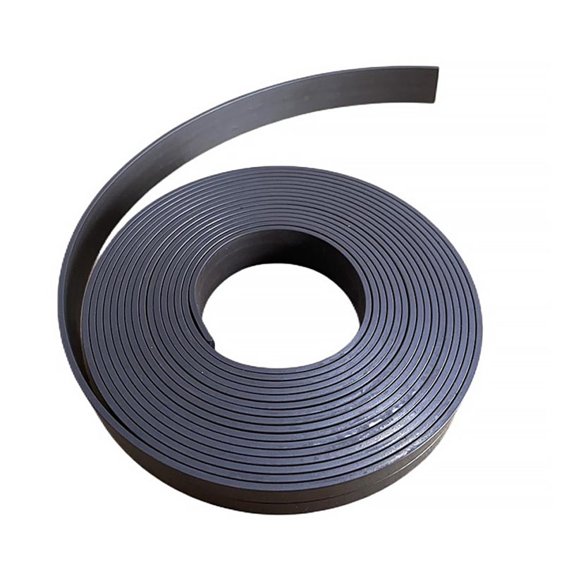
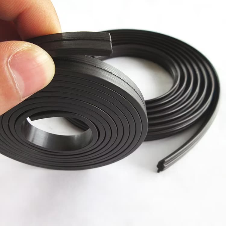
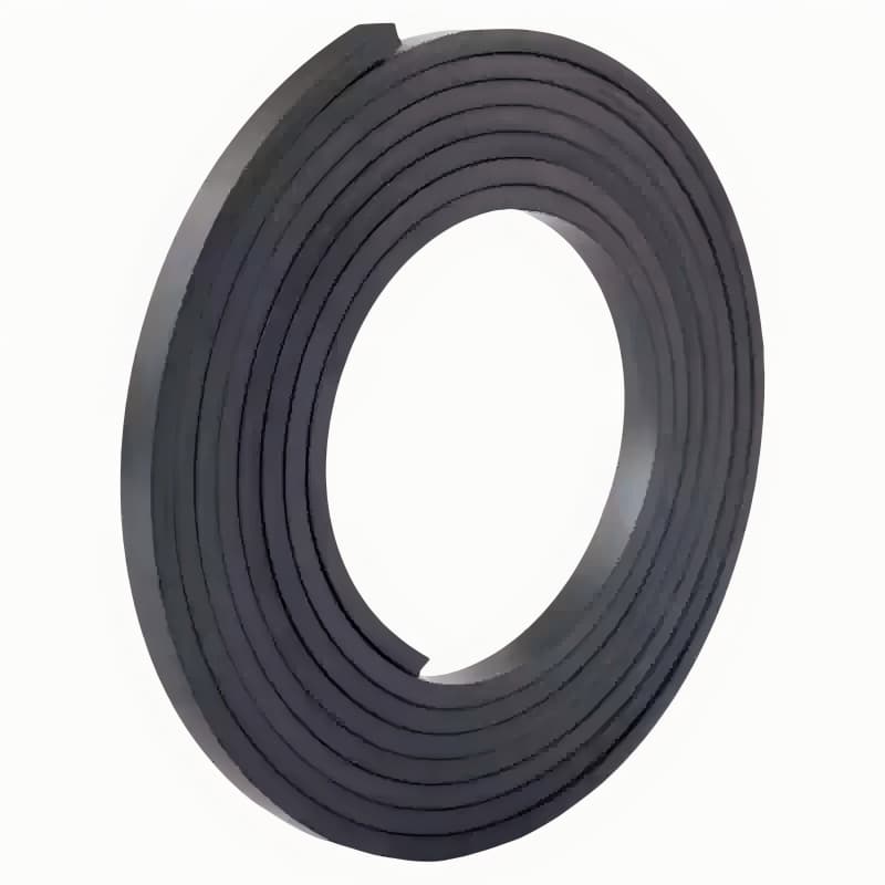
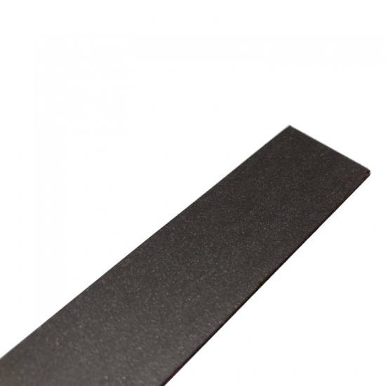
3. Typical Forms of Flexible Magnets in Sensors
| Form | Description | Typical sensor applications |
|---|---|---|
| Multi‑pole strip | Long strip with alternating N‑S‑N‑S poles along its length, attached to a stationary or moving part | Linear displacement sensors, magnetic scales, Hall linear arrays |
| Multi‑pole ring | Circular ring with radial or axial multi‑pole magnetization | Rotary encoders, angle sensors, vehicle speed sensors |
| Single‑pole sheet/strip | Single magnetic pole (N or S) to create a constant field | Proximity switches, magnetic reed switches, level sensors |
| Custom magnetized profile | Custom shape and pole distribution | Special‑path sensors, position feedback systems |
4. Sensor Selection Guide
4.1 Selection by Sensor Type
| Sensor type | Recommended material | Typical pole pitch | Remarks |
|---|---|---|---|
| Hall proximity switch | Ferrite flexible magnet (single‑pole) | — | Needs trigger field typically ≥20 mT – ferrite is sufficient |
| Magnetic speed sensor (variable reluctance) | NdFeB flexible magnet | — | Requires strong bias field; NdFeB gives more stable signal |
| Magnetic encoder (incremental) | NdFeB flexible magnet | 1 – 2 mm | High pole density, clear sine/square wave output |
| Magnetic scale (linear displacement) | NdFeB flexible magnet | 1 – 5 mm | High accuracy, good temperature stability |
| Level sensor (float magnet) | Ferrite flexible magnet | — | Low cost, corrosion resistant |
| Low‑resolution speed sensor | Ferrite flexible magnet | 5 – 10 mm | Low signal accuracy requirement |
4.2 Selection by Signal Strength
4.3 Selection by Temperature Stability
4.4 Selection by Minimum Pole Pitch
5. Technical Specification Comparison Table (Sensor‑Specific, Verified Data)
| Parameter | Ferrite Flexible Magnet (anisotropic multi‑pole) | NdFeB Flexible Magnet (multi‑pole) |
|---|---|---|
| Remanence Br (T) | 0.21 – 0.27 | 0.55 – 0.80 |
| Surface field (1mm thick, 0.5mm air gap, typical) | 80 – 120 mT | 180 – 250 mT |
| Max. energy product (kJ/m³) | 8.8 – 13.6 | 44 – 96 |
| Intrinsic coercivity HcJ (kA/m) | 148 – 319 | 600 – 876 |
| Recommended operating temperature (°C) | -40 ~ +80 | -40 ~ +120 (some +150) |
| Temperature coefficient of Br (%/°C) | -0.2 ~ -0.3 | -0.07 ~ -0.13 |
| Minimum stable pole pitch (mm) | ≥ 3 | ≥ 2 (precision ≥1.5) |
| Density (g/cm³) | 3.6 – 3.8 | 5.5 – 6.2 |
| Hardness | 65 – 85 Shore A | 30 – 60 Shore D |
| Tensile strength (MPa) | 3.8 – 6.9 | ≥ 3.8 |
| Elongation at break (%) | 50 – 80 | ≥ 55 |
📄 Data note: The values above are typical ranges from multiple industry manufacturers’ published specifications. Actual product performance may vary slightly depending on formulation, process, and test conditions.
6. Installation & Usage Guide (Sensor Integration)
6.1 Mounting and Bonding
Surface cleaning: Use isopropyl alcohol or acetone to remove oil, grease, and dust from the mounting surface.
Adhesive selection: For double‑sided tape, use industrial‑grade acrylic tape; for glue, cyanoacrylate or epoxy is recommended.
Magnetized side orientation: The magnetized side of a multi‑pole strip (usually the smooth or marked side) must face the Hall/magnetoresistive element – otherwise the signal will be very weak or phase‑reversed.
6.2 Air Gap Control
The air gap between the sensor and the magnet strip directly affects the magnetic field strength. Every 0.5 mm increase in air gap may reduce field strength by 30–50%.
Recommended air gap range: Ferrite strips ≤ 2 mm; NdFeB strips ≤ 3 mm (adjust according to signal requirements).
6.3 Multi‑pole Strip Orientation
For linear displacement, the length direction of the multi‑pole strip must be parallel to the sensor’s movement direction.
For rotary encoders, the strip or ring must be coaxial with the rotation axis.
Avoid twisting or stretching during installation – keep the strip flat and well‑bonded.
6.4 Temperature and Environmental Protection
Ferrite flexible magnets should not be used continuously above 80°C; NdFeB flexible magnets must not exceed their rated temperature.
In oily or humid environments, choose a laminated or NBR oil‑resistant grade.
⚠️ Note: The strong magnetic field of NdFeB flexible magnets can attract iron filings, which may cause signal interference or physical damage. Clean the surrounding area before installation.
7. Troubleshooting Common Issues (Sensor Applications)
| Problem | Possible cause | Solution |
|---|---|---|
| Weak sensor output signal | Air gap too large | Reduce air gap; use thicker strip or switch to NdFeB |
| Magnetized side facing away from sensor | Check orientation – magnetized side must face sensor | |
| High temperature causing field decay | Lower ambient temperature; use high‑temperature NdFeB grade | |
| Distorted / noisy signal waveform | Uneven pole pitch | Inspect pole pitch accuracy; replace with high‑precision strip |
| Local damage or demagnetization | Replace the strip | |
| Adjacent poles overlapping (pitch too small) | Increase pole pitch; use NdFeB for cleaner pole boundaries | |
| Severe signal drift with temperature | High temperature coefficient of material | Switch to NdFeB flexible magnet with lower temperature coefficient |
| Magnet strip detachment | Poor adhesion | Thoroughly clean surface; use epoxy or high‑grade acrylic tape |
| Rotary encoder counting errors | Ring eccentricity or tilted mounting | Re‑align coaxiality; use a fixture to ensure mounting accuracy |
8. Quality Assurance & Testing (Sensor Grade)
We perform strict outgoing inspections on flexible magnets for sensor applications:
| Test item | Method | Standard |
|---|---|---|
| Thickness / width tolerance | Laser micrometer | ±0.05 mm |
| Surface field distribution | Hall array scanning (2D mapping) | Peak variation ≤ ±5% |
| Multi‑pole pitch | Magnetic scale or optical encoder | ±0.1 mm (precision ±0.05 mm) |
| Inter‑pole angle deviation (ring) | Multi‑probe simultaneous measurement | ≤ ±1° |
| Temperature coefficient | Measured from -40°C to +120°C | Provide temperature‑field curve |
| High/low temperature storage | Rated temperature ±10°C, 24 hours | No cracking, flux change ≤ 3% |
Certifications: ISO 9001, RoHS, REACH. IATF 16949 compliance available on request.
9. Frequently Asked Questions (FAQ)
Q1: How to choose between ferrite and NdFeB flexible magnets for a sensor application?
A: If the required trigger field is ≤100 mT, operating temperature ≤80°C, and pole pitch ≥3 mm, ferrite is the cost‑effective choice. If you need a smaller pole pitch (<3 mm), larger air gap (>2 mm), or better temperature stability, choose NdFeB.
Q2: What is the minimum achievable pole pitch for multi‑pole strips?
A: For ferrite flexible magnets, recommended ≥3 mm. For NdFeB flexible magnets, standard ≥2 mm, and with precision magnetization down to 1.5 mm. However, smaller pitches demand higher accuracy from magnetization equipment and sensor electronics.
Q3: The signal is asymmetric after mounting – why?
A: Common causes are stretching or bending of the strip during installation (changing the pole pitch distribution), or the magnetized side not being parallel to the sensor. Use a fixture or jig to ensure flat, stress‑free mounting.
Q4: What is the service life of flexible magnets in sensors?
A: Within the rated temperature range, ferrite flexible magnets show virtually no decay over time (10+ years). NdFeB flexible magnets are also stable below 100°C; above that, irreversible loss accelerates.
Q5: Can I get free samples of multi‑pole strips with adhesive backing?
A: Yes. Common widths (5, 10, 12.7, 19 mm), thicknesses (1.0, 1.5, 2.0 mm), and standard pitches (2, 2.5, 5 mm) are available as free samples (shipping charged). Custom pitches or shapes require a sample tooling fee.


 IPv6 network supported