What Are You Looking For?
High Stability Anisotropic Rubber Magnet Double-Sided Magnetization for Motor
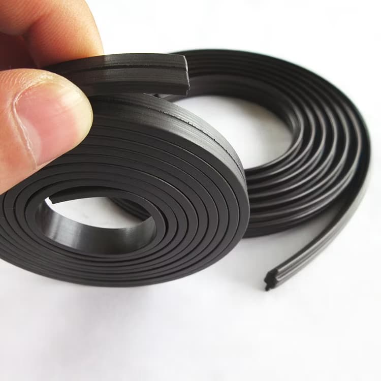
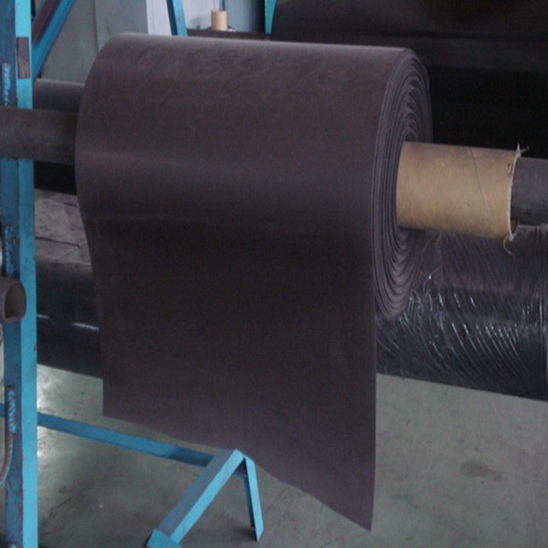
Ferrite rubber magnet – a flexible, low‑cost anisotropic strip for motor rotors, ideal for micro motors, cooling fans, and automotive applications. Replaces sintered tiles with high efficiency and durability.
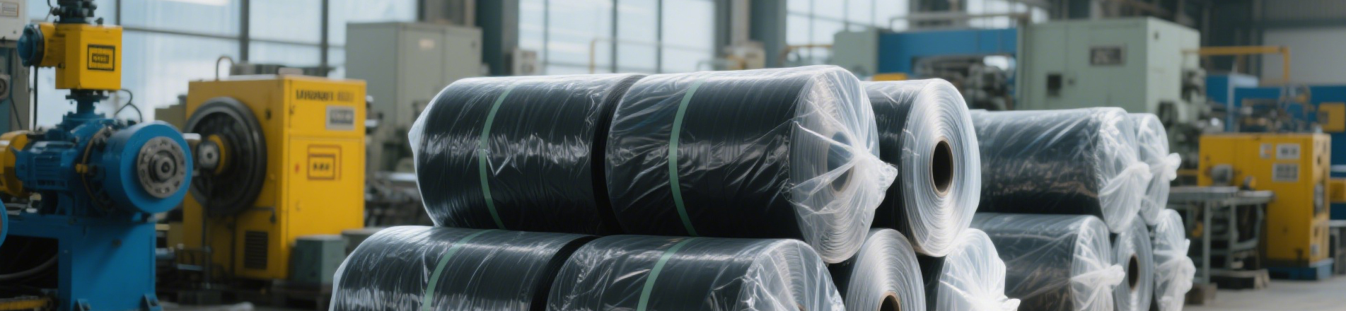
Packaging :
Bulk packing, cartonsPayment :
100% T/T in advancceProduct Origin :
ChinaDelivery time :
15-30 days, depends on the quantityDimensions (DXH) :
CustomsBrand :
KINGSMAGNETCertificates :
ISO/REACH/ROHSMaterial :
Ferrite1. Product Overview
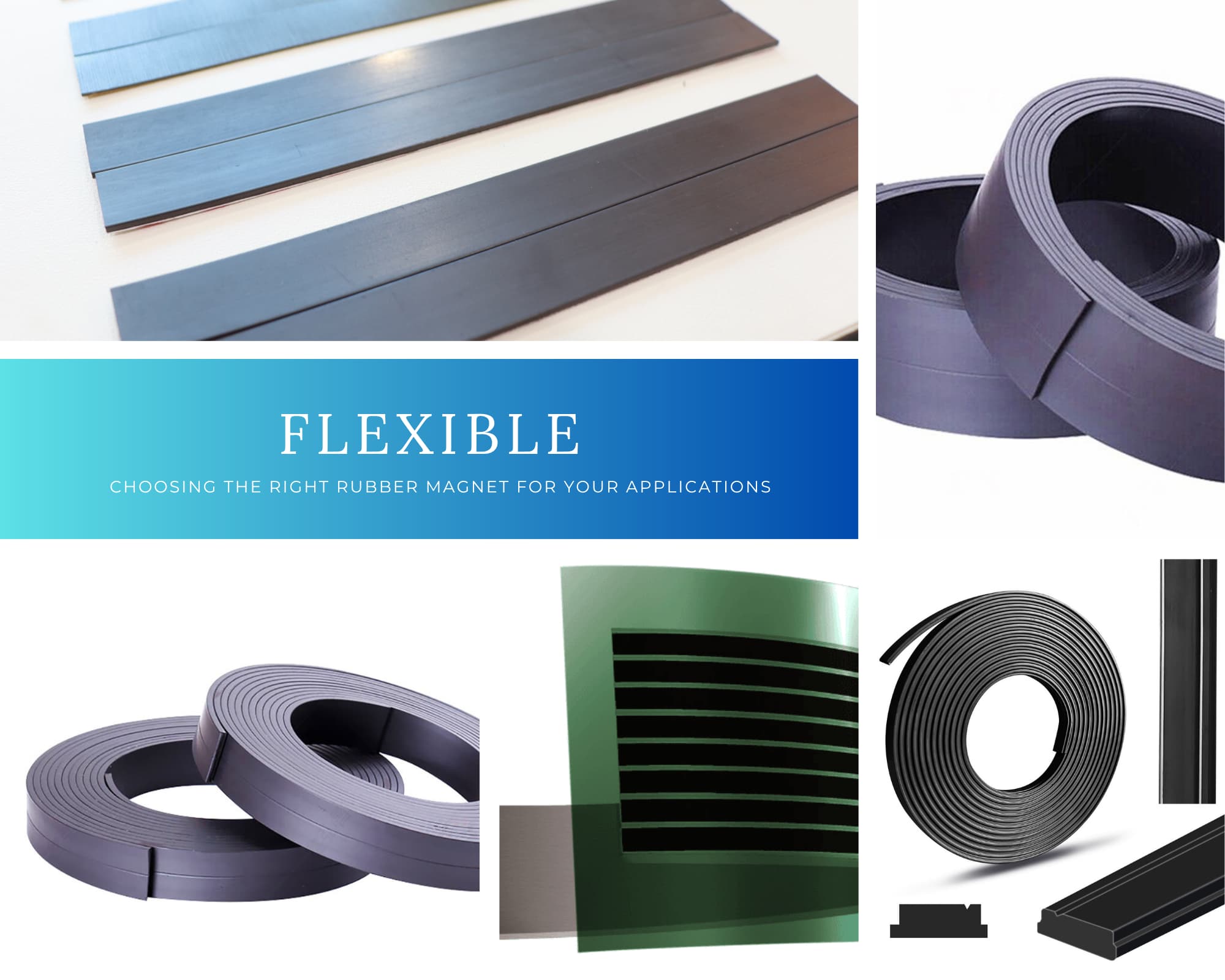
Ferrite rubber magnet is a flexible magnetic material made by compounding bonded ferrite magnetic powder (SrO·6Fe₂O₃) with synthetic rubber or plastic through extrusion, calendering, or injection moulding processes. It combines flexibility, elasticity, and twistability, supporting secondary processing such as cutting, punching, and PVC lamination.
In the motor industry, ferrite rubber magnets are mainly used in micro motors, cooling fan motors, DC motor rotors, and stepper motors. Rubber magnets account for over 40% of the global micro motor market, making them one of the core materials for motor magnetic components.
Core value: Achieve the required magnetic performance at extremely low material cost, while offering unique advantages such as flexible installation, fracture resistance, and silent operation.
2. Key Features and Motor Application Advantages
| Feature | Value for Motor Applications |
|---|---|
| Flexible and bendable | Can be rolled into rings and fitted to curved rotor surfaces without complex processing |
| Fracture resistance | No brittle breakage risk, suitable for high-speed rotation and vibration environments |
| Lightweight | Density of only 3.5–3.7 g/cm³, helping to reduce rotor inertia |
| Electrical insulation | Rubber matrix provides good electrical insulation, suitable for applications requiring electromagnetic shielding |
| Corrosion resistance | Ferrite itself does not rust, eliminating the need for additional coating |
| Extremely low cost | Abundant raw materials, making it the first choice for high-volume motor applications |
| Operating temperature | Standard -40°C to +80°C (some grades up to +100°C) |
| Easy installation | Can be assembled into rings and directly fitted onto the rotor outer surface, significantly improving installation efficiency |
3. Technical Specifications (Motor Application Grade)
3.1 Basic Physical Parameters
| Parameter | Typical Value |
|---|---|
| Material composition | Ferrite powder (SrO·6Fe₂O₃) + rubber matrix (CPE/NBR/PVC) |
| Density | 3.5 – 3.7 g/cm³ |
| Hardness | 65 – 85 Shore A |
| Operating temperature | -40°C ~ +80°C (some +100°C) |
| Thickness range | 0.5 – 10 mm |
| Width range | 5 – 300 mm (customisable) |
| Magnetic powder particle size | 0.5 – 3 μm |
| Matrix Material | Suitable Applications | Advantages | Limitations |
|---|---|---|---|
| CPE (Chlorinated Polyethylene) | General motors, home appliance motors | Low cost, good processability | Not oil-resistant |
| NBR (Nitrile Butadiene Rubber) | Automotive motors, oily environments | Oil-resistant (mineral oils), good heat resistance | Slightly higher cost |
| PVC | Low-cost consumer motors | Extremely low price | Poor flexibility |
| Factor | Consideration |
|---|---|
| ① Magnetisation Type | Isotropic vs. Anisotropic – motors must use anisotropic |
| ② Magnetic Performance Grade | Select (BH)max grade based on torque/power requirements |
| ③ Thickness | Affects magnetic flux, air gap fit, and rotor structural space |
| ④ Matrix Material | CPE (general), NBR (oil-resistant), PVC (low cost) |
| ⑤ Dimensions & Shape | Length, width, curvature – must match rotor dimensions |
5.2 Selection Guide by Motor Type
| Motor Type | Recommended Type | Recommended (BH)max | Recommended Thickness | Recommended Matrix | Notes |
|---|---|---|---|---|---|
| Toy motors | Anisotropic | 1.0–1.3 MGOe | 1.0–1.5 mm | CPE | Cost priority, low torque |
| CPU cooling fan | Anisotropic | 1.3–1.5 MGOe | 2.0–3.5 mm | CPE | Common spec: 202.8×22×3.5mm |
| Ceiling fan | Anisotropic | 1.4–1.6 MGOe | 5.0–6.0 mm | CPE | Requires high energy product |
| Printer stepper | Anisotropic | 1.3–1.5 MGOe | 1.5–2.5 mm | CPE/NBR | High precision required |
| Automotive micro motor | Anisotropic | 1.4–1.6 MGOe | 1.5–3.0 mm | NBR | Oily environment = NBR mandatory |
| Home appliance motor | Anisotropic | 1.3–1.5 MGOe | 2.0–4.0 mm | CPE | General purpose |
| High-speed precision motor | Anisotropic (HP) | 1.5–1.7 MGOe | 1.0–2.0 mm | NBR | High energy product + heat resistance |
5.3 Isotropic vs. Anisotropic – How to Choose for Motors
| Comparison | Isotropic Rubber Magnet | Anisotropic Rubber Magnet |
|---|---|---|
| Surface flux density | 100–400 Gs | 2250–2700 Gs |
| Energy product | 0.5–0.7 MGOe | 1.3–1.6 MGOe |
| Magnetic strength | Weak | Approx. 20% higher than isotropic |
| Operating temperature | ≤60°C | ≤80°C (some +100°C) |
| Suitability for motors | ❌ Not recommended | ✅ Required |
⚠️ Key conclusion: Any motor application that needs to output torque must use Anisotropic rubber magnets. Isotropic rubber magnets do not provide enough magnetic force to drive a motor rotor and are only suitable for non-power applications like fridge magnets and advertising signs.
5.4 Thickness Selection Guide
| Motor Power Level | Recommended Thickness | Applications |
|---|---|---|
| Micro power (<1W) | 0.5 – 1.0 mm | Toy motors, micro vibration motors |
| Small power (1–10W) | 1.0 – 2.0 mm | Cooling fans, small appliance motors |
| Medium power (10–50W) | 2.0 – 4.0 mm | Ceiling fan motors, printer motors |
| High power (>50W) | 4.0 – 6.0 mm | Industrial motors, automotive motors |
Relationship between thickness and magnetic force: With the same material, increasing thickness leads to increased magnetic flux and higher motor torque. However, increased thickness also increases rotor inertia and material cost – performance must be balanced against cost.
| Operating Environment | Recommended Matrix | Reason |
|---|---|---|
| Dry, clean environments (home appliances, fans) | CPE | Lowest cost, good processability |
| Oily environments (automotive engine compartments, machine tools) | NBR | Oil-resistant (mineral oils), heat-resistant |
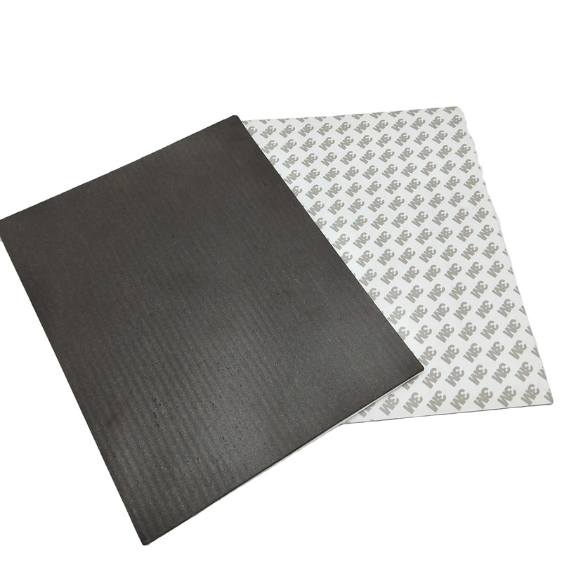
| High humidity/outdoor environments | CPE + PVC lamination | Ferrite itself does not rust; lamination provides enhanced protection |
| Ultra-low-cost consumer motors | PVC | Lowest price, but poorer flexibility |
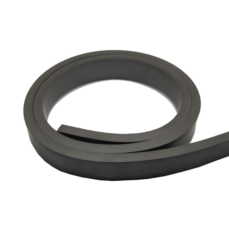
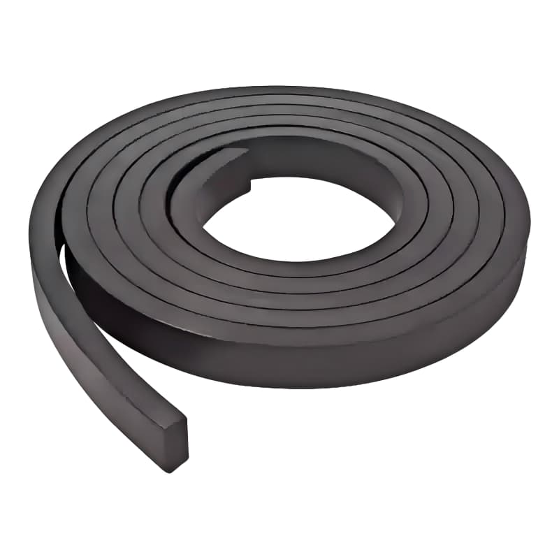
5.6 Forms and Sizing
| Form | Applicable Motors | Sizing Guidelines |
|---|---|---|
| Linear magnetic strips | Assembled into ring-shaped rotors | Length = rotor outer dia. × π; Width = rotor height; Thickness = air gap design value |
| Pre-formed rings | Directly fitted onto the rotor | Inner dia. matches rotor outer dia.; Thickness based on magnetic force requirements |
| Custom die-cut shapes | Special motor structures | Made to drawing specifications |
5.7 Pre-Selection Checklist
Before requesting a quote from a supplier, please confirm the following:
6. Motor Strip Installation Key Points
Ring assembly: Ferrite magnetic strips are typically shipped as straight strips and assembled into rings by the customer during installation. The strip length must precisely equal the rotor outer circumference.
Magnetisation timing: Some motor strips are shipped in an unmagnetised state, fitted into the iron housing or rotor, and then magnetised – this ensures magnetisation saturation and pole symmetry.
Bonding methods:
7. Frequently Asked Questions
Q1: Why can't isotropic rubber magnets be used in motors?
A: Isotropic rubber magnets have a surface flux density of only 100–400 Gs and energy product of only 0.5–0.7 MGOe – insufficient to generate rotor torque. Anisotropic rubber magnets have about 20% higher magnetic force and energy product of 1.3–1.6 MGOe, making them the only choice for motor applications.
Q2: What is the maximum operating temperature of ferrite rubber magnets?
A: Standard is 80°C. Some high-performance grades can reach 100°C. Exceeding the temperature limit causes irreversible demagnetisation.
Q3: Do ferrite rubber magnets rust?
A: No. Ferrite powder is a ceramic material – it does not rust, so no additional coating is required.
Q4: How do I calculate the required strip length for a motor?
A: Strip length = rotor outer diameter × π. Example: rotor outer diameter 64.5mm → strip length ≈ 202.8mm.
Q5: How do I choose between CPE and NBR matrix?
A: Dry, clean environments (home appliances, fans) → CPE, lower cost. Oily environments (automotive motors) → NBR is mandatory.
This High Strength Flexible Neodymium Rubber Magnet Sheet solves the pain point of insufficient magnetic force of ordinary rubber magnets. It adopts high-grade NdFeB magnetic core, with magnetic force far exceeding that of conventional soft magnets, while maintaining flexible, bendable and cuttable characteristics, suitable for multi-scenario adsorption.
Read More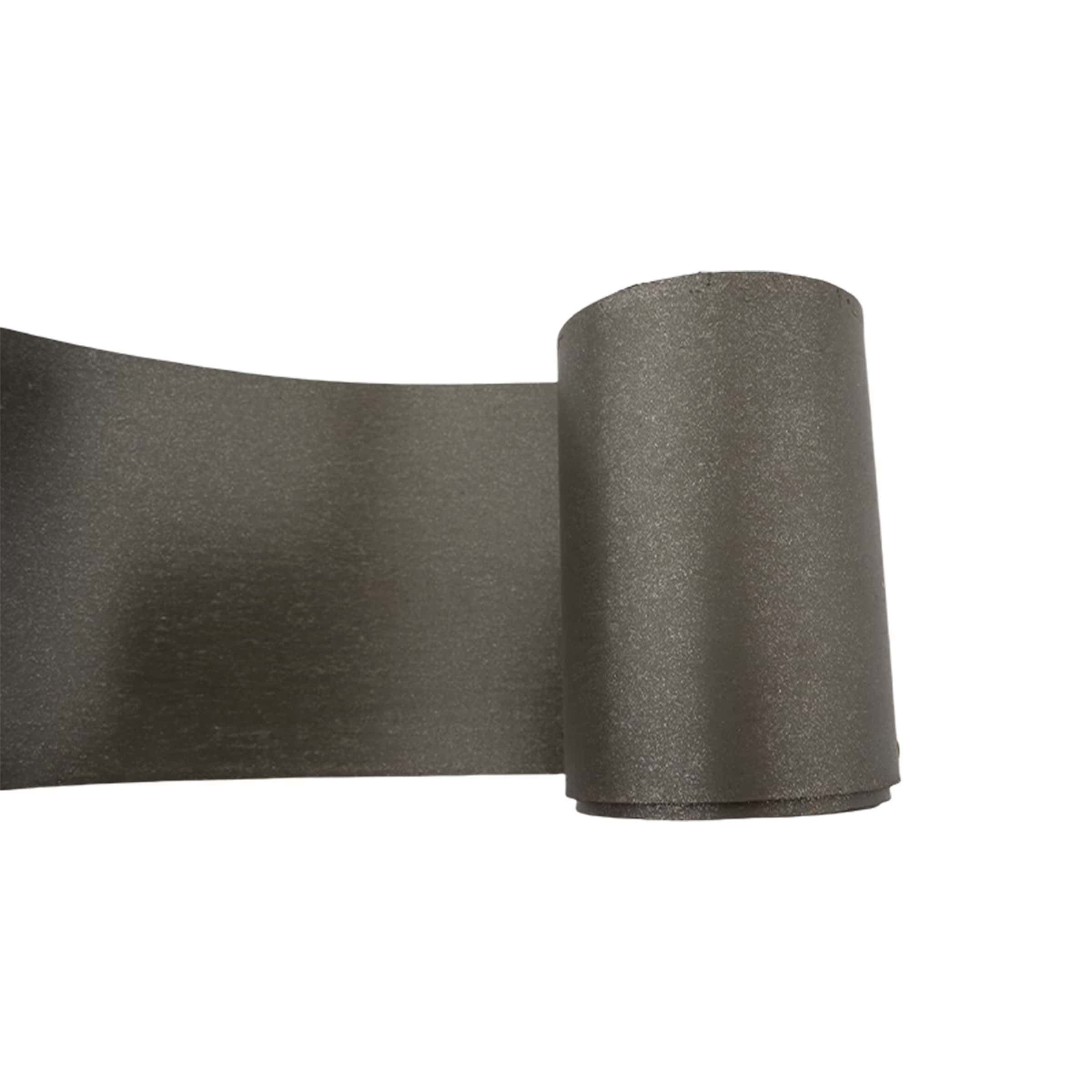
Neodymium flexible magnet combines high‑energy rare‑earth NdFeB powder with a rubber matrix for strong magnetic force and excellent flexibility. It is ideal for industrial applications such as motor rotors, sensors, and encoders where space is limited or surfaces are curved.
Read More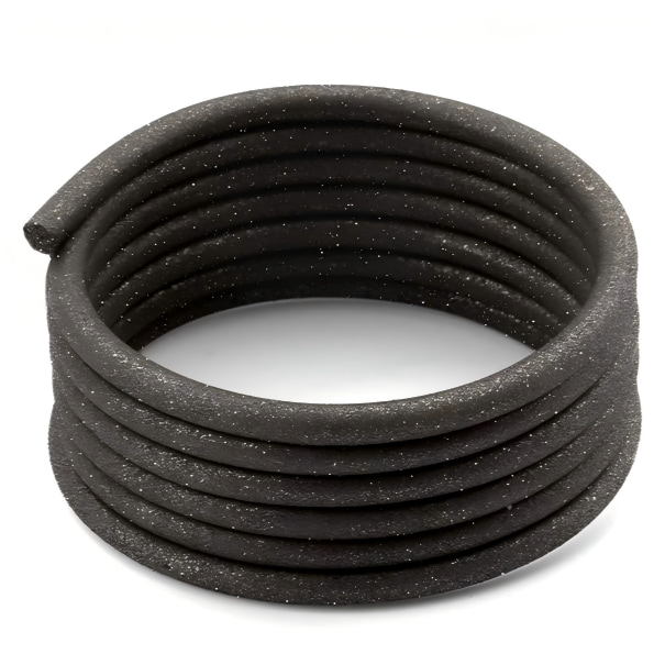
Neodymium flexible magnet combines high‑energy rare‑earth NdFeB powder with a rubber matrix for strong magnetic force and excellent flexibility. It is ideal for industrial applications such as motor rotors, sensors, and encoders where space is limited or surfaces are curved.
Read More
Ferrite rubber magnet – a flexible, low‑cost anisotropic strip for motor rotors, ideal for micro motors, cooling fans, and automotive applications. Replaces sintered tiles with high efficiency and durability.
Read More


 IPv6 network supported